Solidworks Lesson 1.3: Yo Yo
You'll notice in these lessons that I'm using SW 2008. These lessons should be valid for any version 2005+.
Both of these tools are very useful for relating symmetrical geometry about an axis, whether 2D or 3D. If you get any errors during the lesson (highlighted lines and SW will tell you somethings wrong) try deleting some sketch relations. You can tweak the model after we're finished, but make sure you save it since we'll be working with it again later!

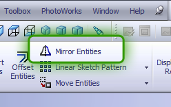
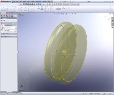
4. Add a centerline and mirror the top half of the yo-yo by selecting the entire sketch (left click and drag) and clicking the axis we want to mirror across. In this case we want to use the vertical centerline that starts at the origin (short line). This will simply reflect all of the lines we selected across that axis. You can dynamically change either side and the other side updates in real time to show the modifications. Pretty sweet!
1. Open a new part in SolidWorks
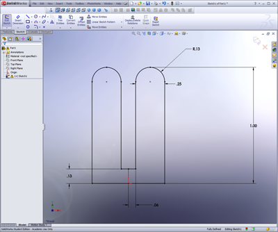
2. Click the ‘Edit Sketch’ button (alternative way to start a sketch), and select the front plane.
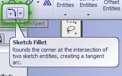
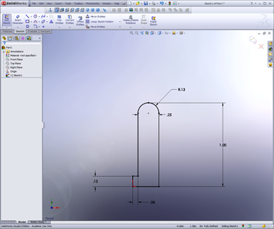
3. Draw ½ of the top of a yo-yo (1/4 of a yo-yo) shape using lines and a sketch-fillet
a. Sketch fillets work the same way as feature fillets, but are faster to calculate
b. They can make geometry changes later on more difficult, so use them wisely
a. Sketch fillets work the same way as feature fillets, but are faster to calculate
b. They can make geometry changes later on more difficult, so use them wisely
4. Add a centerline and mirror the top half of the yo-yo by selecting the entire sketch (left click and drag) and clicking the axis we want to mirror across. In this case we want to use the vertical centerline that starts at the origin (short line). This will simply reflect all of the lines we selected across that axis. You can dynamically change either side and the other side updates in real time to show the modifications. Pretty sweet!
5. Click the ‘exit sketch’ button once your sketch is fully defined
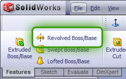
6. Click the ‘rotational extrude’ button and select the bottom line through the origin as our central axis. This is really similar to the mirror, except we are rotating a 2D sketch through space to create a 3D volume. You can do some pretty cool stuff with this tool (try making chess pieces!) so learn how to use it!.
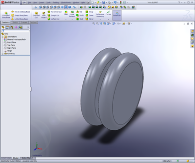
7. Click the green check mark to create the 3d model
8. Play with your virtual yo-yo!
9. We can go back into our feature by right clicking on that feature in the Property Manager and selecting Edit Feature or Edit Sketch, depending on what we want to do.
10. Let’s select Edit Feature, and change the angle from 360 to 180 or 123 or 25.
11. Change your model back to 360, and click okay, or just click the red X.
12. Now let’s try Edit Sketch. This will allow us to go back and change our geometry.
a. Since we used a mirror, we only have to update one quarter of the geometry for everything to work. What a time saver!
b. You can drag the geometry around a little, or enter new dimensions.
c. Once you are satisfied with the changes, click the green check mark.
a. Since we used a mirror, we only have to update one quarter of the geometry for everything to work. What a time saver!
b. You can drag the geometry around a little, or enter new dimensions.
c. Once you are satisfied with the changes, click the green check mark.
Labels: 3d modeling, CAD, CAD lesson, SolidWorks, yo yo
This entry was posted
on Monday, November 24, 2008 at 12:47 AM.
![]()
 Subscribe to DanShope.com