<body bgcolor=#000033"><script type="text/javascript"> function setAttributeOnload(object, attribute, val) { if(window.addEventListener) { window.addEventListener("load", function(){ object[attribute] = val; }, false); } else { window.attachEvent('onload', function(){ object[attribute] = val; }); } } </script> <iframe src="http://www.blogger.com/navbar.g?targetBlogID=4830160160028833890&amp;blogName=DanShope.com&amp;publishMode=PUBLISH_MODE_FTP&amp;navbarType=BLUE&amp;layoutType=CLASSIC&amp;searchRoot=http%3A%2F%2Fblogsearch.google.com%2F&amp;blogLocale=en_US&amp;homepageUrl=http%3A%2F%2Fwww.danshope.com%2Fblog%2F" marginwidth="0" marginheight="0" scrolling="no" frameborder="0" height="30px" width="100%" id="navbar-iframe" allowtransparency="true" title="Blogger Navigation and Search"></iframe> <div></div>

Tuesday, November 24, 2009

Syncing up SolidWorks

As a man on the move who needs access to my data from many different machines, I had struggled to find a good solution to access my SolidWorks files.

The Requirements
  • Should be free or low cost (hopefully not subscription based)
  • Should synchronize files with minimal user input
  • Just works, never needs me to doctor it
I've worked with the professional solutions like Activault, but didn't need quite that level of functionality for my personal use. A subversion utility was intriguing, but generally required too much interaction (commits, updates, etc) for my general workflow.

After manually copying files onto thumb drives, remote desktop-ping, and trying to get a network drive up and running I decided enough was enough. So began a journey through several sync solutions.


Dropbox was my first solution, and worked nearly flawlessly. Updates were transparent, and I could share with other users as well as keep certain folders private. The versioning system was pretty nice and saved me some hassles a few times. I finally ran up against a few limits with the Dropbox service: storage capacity and directory limitations.

Dropbox Storage
You only get 2GB free, which is pretty sweet, but not really enough. My only other option was to purchase a subscription plan, which starts at a hefty $10 per month for 50GB. That's the same as my web hosting, which gets me unlimited storage!!

Dropbox Single Directory
One of Dropbox's most annoying limitations is the use of a single catchall folder. I wanted to retain my file structure which is a complex of files spread across multiple partitions. The more I relied on the service, the more this limitation made the service unusable. It just interrupted my workflow.


This service didn't quite get the full treatment as I was already a little jaded from my Dropbox experience. Overall it was a major step forward - I could impose my own file structure, syncing was seamless, and there were the nice versioning and web-interface features.

Syncplicity is a fantastic service, and probably cuts it for most people. It's gotten rave reviews, it just wasn't the right product for me. If you want access to more than 2 computers, you have to upgrade, again with a monthly subscription fee. It is also Windows only (for the moment)...

Which brings us to the winner,


Not quite fully cross-platform, this service allows syncing between PCs and Macs. Much like Syncplicity, you have full control over directory structure and updates occur immediately when machines are connected to the 'net.


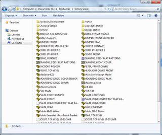
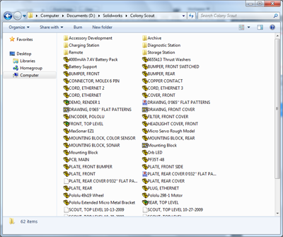
The web interface needs a little work, but for the most part was snappy enough to keep me happy. The syncing occurs fast enough that I get versions of the little temp files (~XXX.sldprt) that SolidWorks creates while you're working. If you've just synced a large number of files and they aren't yet downloaded, double-clicking on the placeholder file will bump it up in the queue. Nicely it also alerts you when the file gets downloaded to your machine.

I found that full versioning control wasn't really necessary for my daily use. A nice trick occurs when you delete a file (this can be done from any synced machine, not just the creator). A deleted file will get moved to the recycle bin on any synced machines. This is generally enough of a safeguard to recover accidently deleted files.


End Result? Happily synced files! I've been using this for the past few days, and it's been quite amazing. I have to remind myself that I can access my files from anywhere. Best of all? It's all free!

Labels: , , , , , , ,


Friday, November 6, 2009

Extending the Scout robot platform

The Scout is a capable platform on its own, able to traverse rough terrain and avoid obstacles at high speeds. Even so, one of the main strengths of the Scout is its (rear) accessory interface.


Many research platforms were designed around a single purpose or only provide the ability for "expansion" cards in the form of networked printed circuit boards. Researchers working on the Scout platform won't be restricted to the current sensor/manipulation package, nor will they be constrained to fixed size add-on modules. The Scout provides power, data, and hardware attachment points to allow a variety of mechanical or sensor add ons. You can see the six threaded hard points in the rear of the vehicle, as well as a thrust bearing for pivoting accessories.

Dumb vs. Smart
The accessory interface attempts to be as non-restrictive as possible while providing both basic and advanced functionality to the designer. To that end we've denoted two classes of accessories, those with "smarts" (onboard processor) and those without. Both classes of accessories must identify their type/function as matched against an accessory database stored on each robot. This allows the OS to configure communications between the ARM and AVR at the bandwidth necessary for desirable performance.

"Dumb" Add-Ons
Dumb accessories are simple devices that only require power and access to an analog (input) or (2) digital I/O. This might be as simple as a wagon with a potentiometer for tracking position and a switch to indicate whether a load is present. Basic I/O pins are provided by the AVR.

"Smart" Add-Ons
A smart accessory has its own on-board microcontroller that handles all the low-level control. An I2C connection straight to the ARM9 processor is provided. Smart accessories can still access the AVR pins, although it should rarely be necessary. The forklift shown below is a "smart accessory" since it requires active control of the lift position and active monitoring of the RFID reader and loading.


Forklift/ Autonomous Distribution Warehouse
My favorite accessory to date, the forklift gives the Scout 0" to 6"+ lift capacity. Pulling tasks off the server, robots will autonomously move packages around, pausing to recharge when necessary. Mobile robots are already in use in semi-automated distribution centers, such as Staples.

The mechanism uses a three stage lift actuated by a cable pulley system. The RFID reader sits behind the carriage. When closed, the forklift does not extend into the sonar's sensing cone, enabling use of rear ranging data. The charging contacts also had to remain exposed so the robots can dock for battery refueling.


Dig & Haul/ Autonomous Excavation

Design to test cooperation between two or more robots, the dig and haul attachments provide an entertaining and challenging application of swarm robotics.

The designs both employ micro servos for actuation. Hauler also uses a load cell (force sensing resistor) to determine when the bucket is full and instruct the digger to halt loading.

Hauler could easily be implemented as a "dumb" accessory, but Digger requires it's own micro due the increased complexity of the control and positioning system.

What next?
Plans are in place to design a simple webcam interface, surveillance package, and a pan/tilt semi-automatic cannon. Have an idea of a sweet accessory? Add your concept to the comments below! I love hearing new ideas, no matter how radical.

Labels: , , , , , , , , , , , , ,


Tuesday, May 12, 2009

SolidWorks Models

If you're not familar with 3DContentCentral.com, hop on over and check it out -- it's a great warehouse for 3D parts from both official manufacturers and common users like you and me.

I have a bunch of "robotics" parts -- gearmotors, brackets, battery packs, motor controllers, etc, as well as some miscellaneous furniture/electronics.

You can view my feed at http://www.3dcontentcentral.com/RssSubscription.aspx?pageFrom=ContribSumm&profileId=248781&userName=Daniel%20Shope

Labels: , , ,


Monday, February 16, 2009

RobOrchestra Update: Bass Drummin' Bot

This past Friday was quite productive for the RobOrchestra team as two instruments were constructed -- the first two for this year.


A few of the guys got together Friday afternoon and built a hurdy-gurdy prototype. The stringed instrument is constructed from a cardboard box and plywood frame. So far the instrument sounds decent when turned, but needs some work on amplification. Using material other than cardboard should definitely help the acoustics...


Fellow RobOrchestra member Andrew Burks and I spent the better part of Friday night (yay social life) working in the shop on the bass drumming robot (as yet unnamed). Andrew made an awesome SolidWorks model which we used as a reference for the parts.

The basic design uses a Bimba air cylinder limited to ~0.5" stroke under 30psi. The cylinder has pivot points at both ends. The pivot points took a lot of machining as we had some pre-existing components that needed to be modified to allow attachment points. One screw up and we were out those parts and had no spares. Fortunately, everything went off without a hitch.

Once the cylinder has pivots at both ends, one end gets attached to the "shoe" of the pedal, the other end inside our robo-leg. We have some sweet plans for decorating said leg -- but until then...


here's a truly amazing picture of yours truly, oh how flattering :-)

Labels: , , , , ,


Sunday, November 30, 2008

SolidWorks Lesson 1.4: Sweeps, Assemblies, & Mates (Yo-Yo String)

Last time we created a yo-yo body and learned how to use rotational extrusions and mirrored sketches.  In this lesson we'll learn how sweeps work, start using assemblies, and learn about the SolidWorks assembly attachments called "mates". At the end we'll have a functional yo-yo...well, sort of! Let's get started!

  1. Create a new document, and choose the Right plane to start your sketch.


  2. Draw a horizontal straight line about 2” long (start at the origin)
  3. Select the spline tool. Click on the end of your last line, and draw a loop.
    1. You may need to play around with this a little since you don’t want your loop to overlap itself at all
    2. We need smooth curvature, so be sure not to make any “sharp” bends


  4. Now selecting the Front plane, start a new sketch. You will need to rotate the view manually either by clicking with the center mouse wheel and dragging across the window, or by using the standard view buttons.
  5. Select the circle tool and sketch a small circle at the origin.
    1. If you created the other lines properly, this should be centered on the straight line.
  6. Dimension this circle with a 0.0625” (1/16”) diameter using the “smart dimensions” tool.


  7. Now click the Sweep/Swept feature button on the Features Toolbar.


  8. Your profile is the circle; your path is the line.
    1. You might see how this could be useful for making complex paths
    2. Feel free to play with this feature when you have some free time!


  9. If you get an error message and SW doesn’t let you create the sweep, there might be something wrong with your model.
    1. Make sure that the circle we are “sweeping” over the long profile is significantly smaller than the line. If the 3D solid will intersect itself because the loop is too small or the circle too large, SW will give you an error message
    2. There may be a sharp angle between the straight line and the loop. To fix this, simply apply a large sketch fillet to the first sketch, say, ½ to 1” radius.
  10. If you went through the yo-yo tutorial, you should now we have a yo-yo string and a body, but they’re in separate documents. We create a SolidWorks assembly document to put our pieces together.


  11. Create a new Assembly document (File, New, Assembly).
  12. Using the “Insert Components” dialog (replaces the property manager), select your yo-yo body or using the browse dialog locate and insert this.
    1. The first part you insert into an assembly will be the “origin”. If you delete this origin part and insert parts later, the assembly will NOT be constrained in 3D space, a big problem for FEA or any physical simulations.
  13. We will use the concept of mates—creating relationships between the parts using the geometry we have created.
    1. For this step we will use a less-useful mate, the “tangent” mate to fix our string to the inner radius of the yoyo.
  14. Not completely constrained, but it will work for this non-functional model (prop)
  15. Your yo-yo is complete!

Labels: , , , , , ,


Tuesday, November 25, 2008

Flutophone 2008: Incremental Update

The flutophone project has been around since the beginning of RobOrchestra, though not in its current form or even with its current name. Started as the "penny-whistle", the project was cobbled together with an old tin whistle, a few solenoids, some plastic fingers, and a little bit of engineering. Penny whistles are basically a long metal tube with holes along the length. Once the instrument was mounted on a base, plastic fingers were built around it that used the "on" or activated setting of the servo to close off an individual hole with a foam ear plug. There were 7 solenoid/arm pairs, one for each hole.

In 2006, a fresh team of undergraduates joined the team, ready to begin and tackle any challege. There were a few problems with this design that the team set out to fix. First, the holes weren't being sealed adequately by the ear plug design. There was some confusion as to whether the soldenoid driven arm didn't have enough force, or if the foam was simply too stiff to conform to the hole and create a good seal. We decided to address both concerns. In order to create a better seal we decided to use some light rubber discs, the kind that you buy to place under objects to prevent a surface from marring. The other aspect of the better seal was switching to a more geometrically desireable instrument, the flutophone. Flutophones have flat surfaces above each hole versus the highly curved surface the penny whistle provided. These changes helped alleviate the biggest challenge - making sure we could produce sound.

The second issue is that the solenoids clacked so loudly, even if the penny whistle/flutophone could get a few notes coaxed out, they would be drowned by metal clanging. We decided to build an enclosure around the solenoids and allow the acutators to pass through a "lid" to the fingers.


The "suspension bridge" design (cutaway view) modeled in SolidWorks

This is the design that we arrived at. We called it the "suspension bridge" approach since we had lots of cables running down sort of like a bridge. This design utilized a main "vertical" shaft that supported the flutophone, finger assembly, and the air tubing. The fingers were mounted to the shaft on dual axles that incorporated spring returns for hole closure. Cables attached to the fingers ran across a pivot point and down into the enclosure such that activating a solenoid would lift the corresponding finger, breaking the seal.

We designed the angles of the instrument such that the cables ran orthogonal (90deg) from the shaft, thus directing all of our force from each solenoid along the action of the finger. This stretched the base to around 18". I made the base out of fiberglass and fiberboard for the strength and light weight characteristics. We determined that the height of the enclosure should be ~3inches to allow clearance for the solenoid plungers. 

Much to our delight, door stops are exactly 3inches long, which provided both the clearance we wanted and had a nice side effect. Since the end of the doorstop is rubber, it provided some shock absorber or damping charactersitics between the "lid" and the enclosure. We also placed felt discs underneath the base to damp the vibrations between the enclosure and the surface it was sitting on. Most of these changes were made to reduce the obnoxious noise the solenoids made.


Plastic composite fingers were strong and stylish

The fingers were a lot of fun to design and construct. I used SolidWorks to model the entire assembly, and created the fingers in this context. I tried to mimic a humanoid shape so that they looked appealing (staying away from the uncanny valley though) and natural. The pivot point of the fingers was designed so that rotating it from its resting position would result in "perfectly" vertical motion (at the first instant). Due to the sine effect there would be little translation of the fingertip side to side, thus most of the displacement would be above the hole surface. If it had been designed differntly, the finger pad would need to rotate across the surface of the flutophone hole, shearing the pad and possibly breaking it off the fingertip.

The fingers were constructed by a three layer laminate. I used some 1/8" red plastic and some thinner white plastic, gluing them together and letting them dry overnight. Then I printed out my design from SolidWorks onto Avery address labels (full adhesive) so that I could simply trace my design while I was cutting each piece out. This was quite the tedious process since each finger was less than 3" long.

2006's design was "pretty" but not functional. We had designed with the best intentions but forgot that oh so helpful acroynm, KISS (Keep It Simple Stupid). You'll probably see me refer to that a lot because so often, the simplest and most elegant solution is the best in terms of cost, manpower, and resources. Plus, a simple solution is easier to change later down the road (in general).


The final design (prototyping material)

Thus, in 2007 I came back with new fervor. I was the last of the original flutophone design group (other members of RobOrchestra were still around), so it became my "pet" project. The design I came up with above is very compact and uses servos for acutation in both directions (open and closed). This was very important since we had tried both actuation==open and acutation==closed with marginal success. The main body bracket that housed the servos contained the entire structure of the new 'bot. We used HS-422 servos (72oz-in torque) which were more than we needed, but I got a good deal on them and we can always reuse them in the future.

The design uses 7 servos, one for each hole. The finger design is similar to that used in the past, just updated for the geometry of the new design. Each servo is connected a finger by a chain and sprocket (1:1) mechanism. For the most part this functions very well, but I had a few issues with keeping tension on the fingers. It was difficult to maintain a calibration on the position relative to the flutophone since there was so much backlash in the system. That part of the design is being updated to fix the backlash issues.

You can see a video demonstration of flutophone on Youtube. In the video, I walk you through the features of the robot and how everything is intended to work. On another video I may upload later, it is actually playing Mary Had a Little Lamb. The great thing about that video is that I was simultaneously the provider of air, program controller, and photographer. Yikes!

The current design is being finalized this year-the main thing that it needed was a few idler pulleys to maintain tension on the chains. Once that is complete she'll be as good as new and ready to play. I'm hoping that we can get the whole thing machined out of plastic so that it is more durable and more precise. We are also working on loading servo controller code onto the RobOrchestra boards, so it can play with the rest of the group. If you want to see more about flutophone, just leave a note in the comments!

Labels: , , , ,


Monday, November 24, 2008

Solidworks Lesson 1.3: Yo Yo

You'll notice in these lessons that I'm using SW 2008. These lessons should be valid for any version 2005+.

In this lesson I'll introduce two new features -- rotational extrusions and mirrored sketches.


Both of these tools are very useful for relating symmetrical geometry about an axis, whether 2D or 3D. If you get any errors during the lesson (highlighted lines and SW will tell you somethings wrong) try deleting some sketch relations. You can tweak the model after we're finished, but make sure you save it since we'll be working with it again later!

1. Open a new part in SolidWorks
2. Click the ‘Edit Sketch’ button (alternative way to start a sketch), and select the front plane.
3. Draw ½ of the top of a yo-yo (1/4 of a yo-yo) shape using lines and a sketch-fillet
a. Sketch fillets work the same way as feature fillets, but are faster to calculate
b. They can make geometry changes later on more difficult, so use them wisely


4. Add a centerline and mirror the top half of the yo-yo by selecting the entire sketch (left click and drag) and clicking the axis we want to mirror across. In this case we want to use the vertical centerline that starts at the origin (short line). This will simply reflect all of the lines we selected across that axis. You can dynamically change either side and the other side updates in real time to show the modifications. Pretty sweet!


5. Click the ‘exit sketch’ button once your sketch is fully defined
6. Click the ‘rotational extrude’ button and select the bottom line through the origin as our central axis. This is really similar to the mirror, except we are rotating a 2D sketch through space to create a 3D volume. You can do some pretty cool stuff with this tool (try making chess pieces!) so learn how to use it!.


7. Click the green check mark to create the 3d model
8. Play with your virtual yo-yo!


9. We can go back into our feature by right clicking on that feature in the Property Manager and selecting Edit Feature or Edit Sketch, depending on what we want to do.
10. Let’s select Edit Feature, and change the angle from 360 to 180 or 123 or 25.
11. Change your model back to 360, and click okay, or just click the red X.
12. Now let’s try Edit Sketch. This will allow us to go back and change our geometry.
a. Since we used a mirror, we only have to update one quarter of the geometry for everything to work. What a time saver!
b. You can drag the geometry around a little, or enter new dimensions.
c. Once you are satisfied with the changes, click the green check mark.

Labels: , , , ,


Friday, November 21, 2008

SolidWorks Lesson 1.2: Your First Part (Donut)

For your first lesson we'll start off with the basics. After this lesson you should know some basic techniques of CAD modeling and begin to understand the Solidworks interface. You might also be hungry, if we do a good job with our donut!

  1. Start with a new part (File, New, Ctrl+N)

  2. Click the ‘Extrude Boss/Base’ button

  3. Now we will need to select a plane – TOP
    1. If you hover over a plane, it will be outlined in red
    2. Clicking on this plane will select it – if you make a mistake, we can exit the sketch and start over

  4. The window will rotate to the top view, centered on the origin

  5. Click on the ‘circle’ tool on the sketch toolbar

  6. Click on the origin, then click again outside of the origin
    1. While you are moving the mouse, you will see the circle being created
    2. We will set the size later on

  7. Now make another larger circle using the same technique.

  8. Now our sketch is created, but we should put sizes on.
    1. Locate the ‘smart dimension’ button on the dimensions toolbar
    2. Click this, then click the inner circle
    3. Drag your mouse away to see the different dimensions (diameter)
    4. Click again to set the diameter
      i.      You can drag this dimension around at any point in time
  1. BEFORE you put a value in, let’s get a dimension between the two circles
    1. Find the “Smart Dimension” button on the toolbar and click on it.
    2. Select both circles, one after the other – order doesn’t matter here.
    3. Do this first so the inner dimension remains the inner circle.                                                              i.      Your initial drawing scale may be off enough that this matters.
    4. We could get have used the offset dimension
      i.      Useful for more complex geometries
  1. Set this to 1 inch.
    1. SW will automatically convert dimensions for you if you are using the suffix (mm, inches, etc.)
    2. You can change the mode (for this document) by going to tools (menu), options (menu), document properties (tab), then units (list), choose IPS
  2. Now double-click on the first dimension, and set it to 1.0 inches
  3. We will now click the “exit sketch” button to get the Extrusion options dialog
    1. Type 1” for the height of the extrusion – the direction doesn’t matter
    2. Click the Green Check (okay button)
  4. You should now have a washer shaped 3D object – you can zoom, rotate, and scale the viewport (dimensions are constrained)
  5. Let’s make a donut – click on the fillet button (rounded corner)
    a. Set the radius to 0.5” (1/2”); select both the top and bottom edge inside & outside edge of our model (4 selections).
    i. The inside and outside faces could also be selected (2 selections)
    b. Click the green check mark.
  1. Now we have a donut!
    1. You can set the color or texture
    2. We can take a bite out of it….but that’s another lesson!

We could have made this several different ways – you could have made a cylinder, and cut a hole in the middle, then filleted. You could have started with a square and rounded the corners, cut out a hole, and then filleted. In general, the more you do with a sketch, the more efficient your model is.

Labels: , , , ,


SolidWorks 101: Lesson 1

I'm starting a series of lessons on beginning CAD with SolidWorks, a great 3D package that I have grown to depend on and enjoy. SolidWorks has some great tutorials within the software you can use - I started writing these tutorials as part of  a one day course I taught for beginners. These are designed for use while using a copy of SolidWorks. So, without further ado, let your introduction to parametric modeling begin!

SolidWorks is a great tool, because you can sit down and learn how to do things yourself.  Some other modeling programs have such a complicated workflow that it is almost necessary to have either a teacher or manual.  SolidWorks is a powerful CAD package, but is presented in a format that is easy to process and understand. I encourage you to play around and learn your own workflow and explore features we may not cover here.

What to take away:
- A basic understanding of how 3D CAD works (terminology, etc) and how to leverage the tools provided to produce simple and functional models.
- “Best practices” or design methodologies to create models that are realistic in terms of constraints and manufacturing techniques
- Design intent – constraining your sketches & dimensions in ways that simplify future modification without losing the reasoning behind certain dimensions (1/2 of width d, etc)

Basic Features
Extrude Boss/Base
Extrude Cut
Sweeps
Rotational Solids
Rotational Cuts
Lofts
Sheet Metal
Fillets/Chamfers

How do we create parts? With sketches - using basic shapes – circles, rectangles, lines, curves – or complex geometry such as splines, repeating patterns, etc.

Solidworks allows rapid model creation by allowing the use of pre-existing geometry to constrain features & sketches.


Lesson 1.1: The Interface


The Solidworks interface is a large window where you create and modify your design, surrounded by toolbars that enhance your interaction with the 3d model.

When starting out, you can use large icons with text labels – as you get more advanced, you can turn the labels off, use small icons, even turn toolbars on and off.  When you feel really comfortable with the program, you can customize toolbars down to the order of icons and set the content for each toolbar.


Throughout the different versions of SolidWorks the icons for different operations have remained the same. The yellowish icons are for operations called "features" -- they modify or create 3D geometries. The blue icons are sketch related operations and create 2D layouts that are used to create 3D geometries through extrusions, cuts, and rotations. You can intuit this from the well-designed buttons that either show an enclosed volume or a line segment.


**Tools you will make use of** the zoom functions and standard views are your best friends! Learn to be comfortable with them, and understand the rotation of your models. I highly recommend that you add the standard views to your toolbar if they aren't already there. Just right click anywhere on the toolbar and select "Standard Views."

Labels: , , ,


Subscribe to RSS Feed
Subscribe to DanShope.com
Who writes This Stuff?
Daniel Shope is the site owner and moderator of DanShope.com, a portal dedicated to robotics and engineering. Dan is currently a student at Carnegie Mellon University and is pursuing dual degrees in Mechanical and Biomedical engineering.

View Daniel Shope's profile on LinkedIn
Advertisements