<body bgcolor=#000033"><script type="text/javascript"> function setAttributeOnload(object, attribute, val) { if(window.addEventListener) { window.addEventListener("load", function(){ object[attribute] = val; }, false); } else { window.attachEvent('onload', function(){ object[attribute] = val; }); } } </script> <iframe src="http://www.blogger.com/navbar.g?targetBlogID=4830160160028833890&amp;blogName=DanShope.com&amp;publishMode=PUBLISH_MODE_FTP&amp;navbarType=BLUE&amp;layoutType=CLASSIC&amp;searchRoot=http%3A%2F%2Fblogsearch.google.com%2F&amp;blogLocale=en_US&amp;homepageUrl=http%3A%2F%2Fwww.danshope.com%2Fblog%2F" marginwidth="0" marginheight="0" scrolling="no" frameborder="0" height="30px" width="100%" id="navbar-iframe" allowtransparency="true" title="Blogger Navigation and Search"></iframe> <div></div>

Sunday, November 30, 2008

SolidWorks Lesson 1.4: Sweeps, Assemblies, & Mates (Yo-Yo String)

Last time we created a yo-yo body and learned how to use rotational extrusions and mirrored sketches.  In this lesson we'll learn how sweeps work, start using assemblies, and learn about the SolidWorks assembly attachments called "mates". At the end we'll have a functional yo-yo...well, sort of! Let's get started!

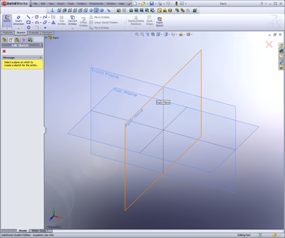
  1. Create a new document, and choose the Right plane to start your sketch.


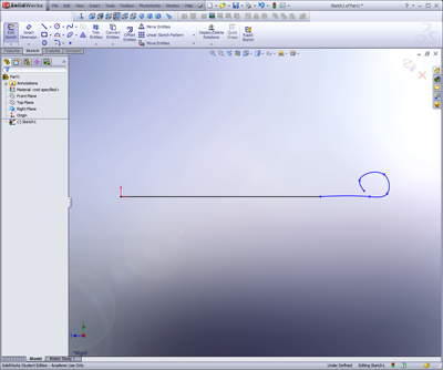
  2. Draw a horizontal straight line about 2” long (start at the origin)
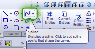
  3. Select the spline tool. Click on the end of your last line, and draw a loop.
    1. You may need to play around with this a little since you don’t want your loop to overlap itself at all
    2. We need smooth curvature, so be sure not to make any “sharp” bends


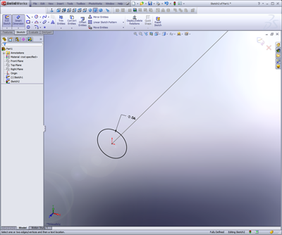
  4. Now selecting the Front plane, start a new sketch. You will need to rotate the view manually either by clicking with the center mouse wheel and dragging across the window, or by using the standard view buttons.
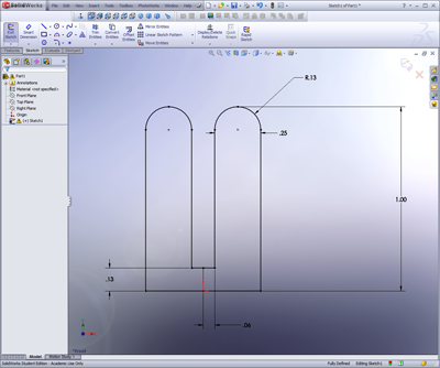
  5. Select the circle tool and sketch a small circle at the origin.
    1. If you created the other lines properly, this should be centered on the straight line.
  6. Dimension this circle with a 0.0625” (1/16”) diameter using the “smart dimensions” tool.


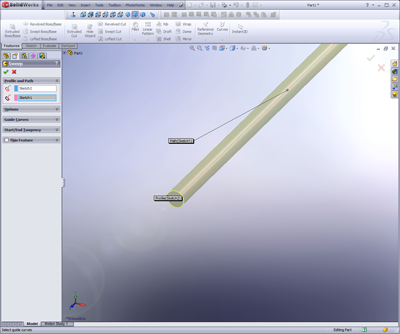
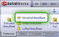
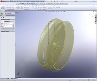
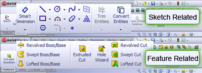
  7. Now click the Sweep/Swept feature button on the Features Toolbar.


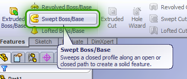
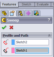
  8. Your profile is the circle; your path is the line.
    1. You might see how this could be useful for making complex paths
    2. Feel free to play with this feature when you have some free time!


  9. If you get an error message and SW doesn’t let you create the sweep, there might be something wrong with your model.
    1. Make sure that the circle we are “sweeping” over the long profile is significantly smaller than the line. If the 3D solid will intersect itself because the loop is too small or the circle too large, SW will give you an error message
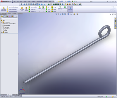
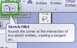
    2. There may be a sharp angle between the straight line and the loop. To fix this, simply apply a large sketch fillet to the first sketch, say, ½ to 1” radius.
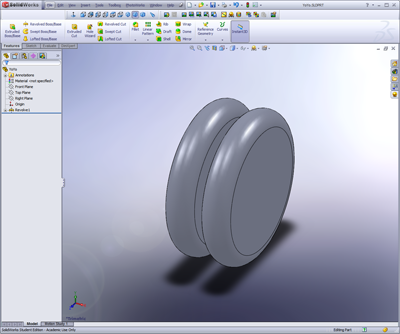
  10. If you went through the yo-yo tutorial, you should now we have a yo-yo string and a body, but they’re in separate documents. We create a SolidWorks assembly document to put our pieces together.


  11. Create a new Assembly document (File, New, Assembly).
  12. Using the “Insert Components” dialog (replaces the property manager), select your yo-yo body or using the browse dialog locate and insert this.
    1. The first part you insert into an assembly will be the “origin”. If you delete this origin part and insert parts later, the assembly will NOT be constrained in 3D space, a big problem for FEA or any physical simulations.
  13. We will use the concept of mates—creating relationships between the parts using the geometry we have created.
    1. For this step we will use a less-useful mate, the “tangent” mate to fix our string to the inner radius of the yoyo.
  14. Not completely constrained, but it will work for this non-functional model (prop)
  15. Your yo-yo is complete!

Labels: , , , , , ,


Monday, November 24, 2008

Solidworks Lesson 1.3: Yo Yo

You'll notice in these lessons that I'm using SW 2008. These lessons should be valid for any version 2005+.

In this lesson I'll introduce two new features -- rotational extrusions and mirrored sketches.


Both of these tools are very useful for relating symmetrical geometry about an axis, whether 2D or 3D. If you get any errors during the lesson (highlighted lines and SW will tell you somethings wrong) try deleting some sketch relations. You can tweak the model after we're finished, but make sure you save it since we'll be working with it again later!

1. Open a new part in SolidWorks
2. Click the ‘Edit Sketch’ button (alternative way to start a sketch), and select the front plane.
3. Draw ½ of the top of a yo-yo (1/4 of a yo-yo) shape using lines and a sketch-fillet
a. Sketch fillets work the same way as feature fillets, but are faster to calculate
b. They can make geometry changes later on more difficult, so use them wisely


4. Add a centerline and mirror the top half of the yo-yo by selecting the entire sketch (left click and drag) and clicking the axis we want to mirror across. In this case we want to use the vertical centerline that starts at the origin (short line). This will simply reflect all of the lines we selected across that axis. You can dynamically change either side and the other side updates in real time to show the modifications. Pretty sweet!


5. Click the ‘exit sketch’ button once your sketch is fully defined
6. Click the ‘rotational extrude’ button and select the bottom line through the origin as our central axis. This is really similar to the mirror, except we are rotating a 2D sketch through space to create a 3D volume. You can do some pretty cool stuff with this tool (try making chess pieces!) so learn how to use it!.


7. Click the green check mark to create the 3d model
8. Play with your virtual yo-yo!


9. We can go back into our feature by right clicking on that feature in the Property Manager and selecting Edit Feature or Edit Sketch, depending on what we want to do.
10. Let’s select Edit Feature, and change the angle from 360 to 180 or 123 or 25.
11. Change your model back to 360, and click okay, or just click the red X.
12. Now let’s try Edit Sketch. This will allow us to go back and change our geometry.
a. Since we used a mirror, we only have to update one quarter of the geometry for everything to work. What a time saver!
b. You can drag the geometry around a little, or enter new dimensions.
c. Once you are satisfied with the changes, click the green check mark.

Labels: , , , ,


Friday, November 21, 2008

SolidWorks Lesson 1.2: Your First Part (Donut)

For your first lesson we'll start off with the basics. After this lesson you should know some basic techniques of CAD modeling and begin to understand the Solidworks interface. You might also be hungry, if we do a good job with our donut!

  1. Start with a new part (File, New, Ctrl+N)

  2. Click the ‘Extrude Boss/Base’ button

  3. Now we will need to select a plane – TOP
    1. If you hover over a plane, it will be outlined in red
    2. Clicking on this plane will select it – if you make a mistake, we can exit the sketch and start over

  4. The window will rotate to the top view, centered on the origin

  5. Click on the ‘circle’ tool on the sketch toolbar

  6. Click on the origin, then click again outside of the origin
    1. While you are moving the mouse, you will see the circle being created
    2. We will set the size later on

  7. Now make another larger circle using the same technique.

  8. Now our sketch is created, but we should put sizes on.
    1. Locate the ‘smart dimension’ button on the dimensions toolbar
    2. Click this, then click the inner circle
    3. Drag your mouse away to see the different dimensions (diameter)
    4. Click again to set the diameter
      i.      You can drag this dimension around at any point in time
  1. BEFORE you put a value in, let’s get a dimension between the two circles
    1. Find the “Smart Dimension” button on the toolbar and click on it.
    2. Select both circles, one after the other – order doesn’t matter here.
    3. Do this first so the inner dimension remains the inner circle.                                                              i.      Your initial drawing scale may be off enough that this matters.
    4. We could get have used the offset dimension
      i.      Useful for more complex geometries
  1. Set this to 1 inch.
    1. SW will automatically convert dimensions for you if you are using the suffix (mm, inches, etc.)
    2. You can change the mode (for this document) by going to tools (menu), options (menu), document properties (tab), then units (list), choose IPS
  2. Now double-click on the first dimension, and set it to 1.0 inches
  3. We will now click the “exit sketch” button to get the Extrusion options dialog
    1. Type 1” for the height of the extrusion – the direction doesn’t matter
    2. Click the Green Check (okay button)
  4. You should now have a washer shaped 3D object – you can zoom, rotate, and scale the viewport (dimensions are constrained)
  5. Let’s make a donut – click on the fillet button (rounded corner)
    a. Set the radius to 0.5” (1/2”); select both the top and bottom edge inside & outside edge of our model (4 selections).
    i. The inside and outside faces could also be selected (2 selections)
    b. Click the green check mark.
  1. Now we have a donut!
    1. You can set the color or texture
    2. We can take a bite out of it….but that’s another lesson!

We could have made this several different ways – you could have made a cylinder, and cut a hole in the middle, then filleted. You could have started with a square and rounded the corners, cut out a hole, and then filleted. In general, the more you do with a sketch, the more efficient your model is.

Labels: , , , ,


SolidWorks 101: Lesson 1

I'm starting a series of lessons on beginning CAD with SolidWorks, a great 3D package that I have grown to depend on and enjoy. SolidWorks has some great tutorials within the software you can use - I started writing these tutorials as part of  a one day course I taught for beginners. These are designed for use while using a copy of SolidWorks. So, without further ado, let your introduction to parametric modeling begin!

SolidWorks is a great tool, because you can sit down and learn how to do things yourself.  Some other modeling programs have such a complicated workflow that it is almost necessary to have either a teacher or manual.  SolidWorks is a powerful CAD package, but is presented in a format that is easy to process and understand. I encourage you to play around and learn your own workflow and explore features we may not cover here.

What to take away:
- A basic understanding of how 3D CAD works (terminology, etc) and how to leverage the tools provided to produce simple and functional models.
- “Best practices” or design methodologies to create models that are realistic in terms of constraints and manufacturing techniques
- Design intent – constraining your sketches & dimensions in ways that simplify future modification without losing the reasoning behind certain dimensions (1/2 of width d, etc)

Basic Features
Extrude Boss/Base
Extrude Cut
Sweeps
Rotational Solids
Rotational Cuts
Lofts
Sheet Metal
Fillets/Chamfers

How do we create parts? With sketches - using basic shapes – circles, rectangles, lines, curves – or complex geometry such as splines, repeating patterns, etc.

Solidworks allows rapid model creation by allowing the use of pre-existing geometry to constrain features & sketches.


Lesson 1.1: The Interface


The Solidworks interface is a large window where you create and modify your design, surrounded by toolbars that enhance your interaction with the 3d model.

When starting out, you can use large icons with text labels – as you get more advanced, you can turn the labels off, use small icons, even turn toolbars on and off.  When you feel really comfortable with the program, you can customize toolbars down to the order of icons and set the content for each toolbar.


Throughout the different versions of SolidWorks the icons for different operations have remained the same. The yellowish icons are for operations called "features" -- they modify or create 3D geometries. The blue icons are sketch related operations and create 2D layouts that are used to create 3D geometries through extrusions, cuts, and rotations. You can intuit this from the well-designed buttons that either show an enclosed volume or a line segment.


**Tools you will make use of** the zoom functions and standard views are your best friends! Learn to be comfortable with them, and understand the rotation of your models. I highly recommend that you add the standard views to your toolbar if they aren't already there. Just right click anywhere on the toolbar and select "Standard Views."

Labels: , , ,


Subscribe to RSS Feed
Subscribe to DanShope.com
Who writes This Stuff?
Daniel Shope is the site owner and moderator of DanShope.com, a portal dedicated to robotics and engineering. Dan is currently a student at Carnegie Mellon University and is pursuing dual degrees in Mechanical and Biomedical engineering.

View Daniel Shope's profile on LinkedIn
Advertisements