<body bgcolor=#000033"><script type="text/javascript"> function setAttributeOnload(object, attribute, val) { if(window.addEventListener) { window.addEventListener("load", function(){ object[attribute] = val; }, false); } else { window.attachEvent('onload', function(){ object[attribute] = val; }); } } </script> <iframe src="http://www.blogger.com/navbar.g?targetBlogID=4830160160028833890&amp;blogName=DanShope.com&amp;publishMode=PUBLISH_MODE_FTP&amp;navbarType=BLUE&amp;layoutType=CLASSIC&amp;searchRoot=http%3A%2F%2Fblogsearch.google.com%2F&amp;blogLocale=en_US&amp;homepageUrl=http%3A%2F%2Fwww.danshope.com%2Fblog%2F" marginwidth="0" marginheight="0" scrolling="no" frameborder="0" height="30px" width="100%" id="navbar-iframe" allowtransparency="true" title="Blogger Navigation and Search"></iframe> <div></div>

Wednesday, June 24, 2009

Sharp IR Rangefinders and Arduino: Make your Robot Smarter

Adding distance or proximity sensors to your robot is a great way to start exploring your environment intelligently. Rangefinders allow a non-contact method of “seeing” obstacles and can be employed in mapping and maze solving as well.

The Sharp family of infrared (IR) rangefinders is very popular amongst hobby roboticists because they are low-cost and easy to interface with (Voltage, Ground, and Signal). These hook up to a single analog input pin on the Arduino or similar microcontroller systems. There are a few caveats to watch out for though.

If your application is very time sensitive and needs tightly controlled, you’ll want to find out how long polling your sensor(s) takes. The Sharp sensors output an analog value (as a voltage), but microcontrollers only understand digital values (1 or 0), so that analog value has to be converted. Analog to digital conversion is pretty fast, but it can introduce some delays.

The sensors are also very noisy, meaning the analog output signal has a lot of "jitter" -- 20cm does not always equal 280, etc. Your code will have to account for this jitter, so you'll need to collect some real-world values to build your sensor model. This problem is exacerbated by the next issue, but can be overcome with a little bit of thought and time. I don't provide you the solution here because it's really dependent on your application. There is, however, a tool to help you evaluate your sensors (see below).

Moving on, take a look at this graph:

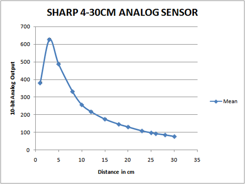
You’ll notice something interesting here – the graph has a weird curve and isn’t linear at all. This becomes tricky when trying to teach the robot to understand distance from the analog output of the sensor.

There are a few ways to get around this. If all you want is a simple threshold say “nothing closer than 20cm” then you can simply run a few tests with an object placed 20cm away from the sensor, and then hardcode that value into your program. Generally it’s a bit more complicated, if you want the program to understand varying distance.

Method 1:
Approach: Find a best-fit curve (generally exponential or polynomial) using a statistics package (Excel, R, Minitab)
Pros: Easy to implement, gets you started fast.
Cons: Requires floating point math, which isn’t natively supported by most microcontrollers. You can still use floating point, but it’s slow and inefficient in most cases.

Method 2:
Approach: Gather some data points and create a look up table of values. Your code will linearly interpolate values between each data point (ie, 5cm=600, 10cm=300, etc).
Pros: Uses integer math which is fast and efficient
Cons: Takes up more memory and doesn’t give exact values

Method 2 is the preferred approach as most embedded system developers take great pains to avoid floating point math. You can have some floating point math on the Arduino and be alright. I have a large (6KB) program right now that has floating point littered all over the place (it’s necessary for this code) and execution time runs just fine.

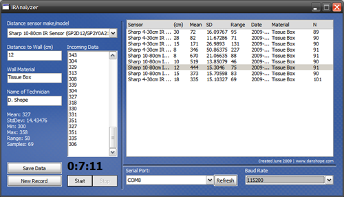
To help with gathering your data for both method 2 and simple thresholding I wrote a quick little application that interfaces with the Arduino’s serial connection. This app will pull your data in and calculate some basic statistics such as standard deviation, mean average, and range of values. You can store the data for future computation and reference.

Download the IRanalzyer at http://www.danshope.com/calton/ir.html

To use the IRanalyzer you need to send values from the Arduino. Here’s a sample sketch to get you started:


#define SerialSpeed 115200 //typical values are 9600 or 115200
#define SampFrequency 10 //sampling frequency in Hz (cycles per second)
#define AnalogPIN 0 //define your pin here

int mDelay;

void setup()
{
Serial.begin(SerialSpeed);
mDelay = 1000/SampFrequency; //calculate delay for proper sampling rate
}

void loop()
{
delay(mDelay); //delay in milliseconds
Serial.println( analogRead(AnalogPIN) ); //reads the analog port and prints value over serial
}

Labels: , , , , , , , , , , , ,


Wednesday, June 3, 2009

Inside the $400 Colony Scout: Robot on a Budget

Now that I posted some videos of the Colony Scout in action, I’ll discuss the platform in a little more detail.

The basics: It’s a compact (4.75”x6”), four wheel-drive robot equipped with an array of IR distance sensors, automatic recharging capability, and other features yet to come. The current talk is to use an ARM7 based board running at 40MHz, paired with an unspecified ATMega for additional I/O.

Some background: The goal of the Colony project at the CMU Robotics Club is to develop a low cost swarm robotics platform capable of structured coordination to carry out tasks too difficult for a single machine.

Colony has been around for several years and has made great strides with a few robot upgrades along the way. The team is prepping the Scout as a potential replacement for the current ATMega 128L based robots.

The goal: The Scout is a deviation from the 2-wheel differential drive robots used in the past. While a common and versatile form factor, the two wheeled platform balked at any non-level terrain. Even driving up ramps or over wires can become an issue. Scout is designed to expand the exploration options beyond level and rectangular environments.

What’s new? Faster processors and an efficient code base will permit the Scout to actively respond to a complex environment. The new sensor array extends the current 5 IR sensors to 7 for additional range and cliff detection. A bump switch returns for the front bumper to detect obstacle collision (useful when purposely pushing objects).

Each of the Pololu wheels comes equipped with a quadrature encoder that gives ~3mm linear accuracy. The 10x12mm micro metal gearmotors are lighter, faster, and stronger than the Solarbotics GM8s on the current robots. Using four motors does draw more current, so the battery is upped from a 6V 2200mAh NiMH pack to a beefy 7.2V 4000mAh Li-Ion pack.

Conclusion: The Colony Scout is a tough little machine that can cross rough terrain while employing a multitude of sensors, all for a sub-$400 cost per robot. Plans are in place to make the robots “smarter” than ever before, and able to respond to the environment faster and in a more coordinated manner.

Summer 2009 is all about prototype testing – learning about the platform and its capabilities and limitations, so stay tuned – More videos and posts will be coming your way!

What do you think? What types of functionality, from line sensing to 3D mapping, do you think a cheap robot should have?

See http://www.danshope.com/blog/2009/05/putting-colony-scout-robot-through-its.html for more pics and vids on the Colony Scout.

Labels: , , , , , , ,


Sunday, May 31, 2009

Putting the Colony Scout robot through its paces

The new Colony Scout platform was up and running for a few hours today as I continued testing the AWD system. Scout is a prototype platform for swarm robotics at the Carnegie Mellon Robotics Club.


We remade the baseplate out of 6061 aluminum on the CNC mill as the previous handcut plate was too soft and imprecise. I wanted the alignment of all the motors/wheels to be as consistent as possible for straight tracking with minimal correction from software.

The headers you see sticking up beside each wheel are for quadrature encoders - the encoders give the robot about 3mm linear resolution, which is decent for a vehicle of this size.


Another exciting component added today was the rocker, which allows the front and rear axles to swivel (vertically). This allows all four wheels to contact the ground during most terrain crossing, improving traction. The updated platform outperforms the Scout of two days ago, which featured a rigid baseplate.


The new components have a high degree of polish accomplished by good design and machining practices. Our club machine shop allows us to turn out quality parts and have a fast turn around time from concept to prototype.


Click through to http://www.youtube.com/watch?v=ePaPGyjW2uk to watch the video in HD.

There's also some great tests on http://www.youtube.com/watch?v=fyRmg570KJw from a few days ago.

Keep tuned for more updates this week!

Labels: , , , , , , , , ,


Thursday, May 28, 2009

Quick Gear Reduction Design Reference

A properly designed gear train is very important for effective power transmission and efficient usage of your power supply. Often overlooked for hobby robotics, putting a little thought into your gear train can go a long way toward a successful design.

Many factors need to be taken into consideration, such as gear material, gear manufacturing method, speed, loading, and space considerations, as well as desired noise level and configuration (offset, concentric, etc). There are books of equations governing tooth profiles and gearing efficiency but for most work you’ll find an involute tooth profile governed by the Lewis formula with an American Gear Manufacturers Association (AGMA) dynamic correction factor.

The following information is provided as a generalized reference to gear train design and assumes you are familiar with basic gear geometry and types. For serious work use the linked references as they are more comprehensive and thorough.

Spur Gears

  • High efficiency, high power (98-99% eff)
  • Lowest cost for machining
  • Exert high radial loads on bearings
  • Offset drive

Helical Gears

  • High efficiency, very high power (97-99% eff)
  • Loses some efficiency due to high axial load and tooth slipping
  • Geometry allows full tooth contact à good for high power transfer
  • Quiet running (increase helix angle for quieter transmission)
  • Offset drive

Planetary/Epicyclical Gearbox

  • Fairly high efficiency, high power
  • Low radial loading from concentric design
  • Complicated assembly and varying torque outputs
  • Concentric drive

Harmonic Drive

  • Moderately efficient
  • Very high gear reduction in a compact size (30:1 to 350:1)
  • Zero backlash (30% of teeth always in contact)
  • Concentric drive

Bevel Gears

  • High efficiency (97-99%)
  • Used where right angle drive is required
  • Typically 1:1 to 6:1 ratios used
  • Complex tooth profile can be difficult to machine

Worm Mesh

  • Poor efficiency
  • High gear reduction in a compact size
  • Non back-driveable
  • Unsuitable for low velocity ratios
  • Offset drive (90deg)

See http://www.engineersedge.com/gear_design.htm for a detailed table on different gear setups.

Notes:

1) Higher pressure angle increase radial loading on bearings (called separation force), but decreases stress on gear teeth and minimizes bending. A higher pressure angle results in a lower contact ratio and thus a noisier gear train.

2) The most common pressure angle is 20deg. Case hardened 25deg teeth can carry about 20% more torque than a 20deg form. Because of factors discussed in Note 1, a 22.5deg form is a good compromise that provides about 11% more torque carrying capacity.

3) Gear efficiency in multiple stages (spur gear) is calculated by the product of the efficiency of each stage: Estage1*Estage2*100=Etotal à 0.98*0.98*100=96.04% efficiency.

4) Hunting ratio: non-integer ratio where a given pinion tooth will touch every tooth on the gear before touching the same gear tooth twice (13:48 is a hunting ratio, 12:48 is not). This design reduces wear and tear on individual teeth as the gear teeth mesh at different points from revolution to revolution.

References:
1. Dudley, Darle W. Handbook of Practical Gear Design. CRC Press. 1994.
2. RoyMech Engineering Reference. http://www.roymech.co.uk/Useful_Tables/Drive/Gear_Efficiency.html
3. SDP/SI Tech Library. http://www.sdp-si.com/Sdptech_lib.htm.
4. Epicyclic Gearing. Wikipedia. http://en.wikipedia.org/wiki/Epicyclic_gearing
5. Basics of Harmonic Drives. http://www.powertransmission.com/issues/0706/harmonic.htm

Labels: , , , , , , , ,


Thursday, March 12, 2009

Do You Know How to Arduino?

I had a great day prototyping with new Arduino Duemilanove. Other than the frustaingly long name we got along pretty well!

The board came from SparkFun along with a protoboard -- I didn't get the protoshield yet, but it's only another $16 so it might be a future purchase. Also arriving today was the compact accelerometer breakout board from RobotShop. One box came by snail mail, the other by UPS, so it was quite exciting when they arrived literally within minutes of each other.

The Duemilanove is a great board -- solid components, automatic power switching, plenty of IO, and an upgraded ATmega chip. I'm definitely going to like having the extra storage on board for my new project.

I had to do a lot of fiddling to get the accelerometer to work well, but most of this was software tweaking. The actual circuitry took all of fifteen minutes and the arudino sketch was really fast.

#include

void setup()
{
  Serial.begin(115200);
}

void loop()
{
  Serial.print("X");
  Serial.print(analogRead(2));
  Serial.print(",Y");
  Serial.print(analogRead(1));
  Serial.print(",Z");
  Serial.print(analogRead(0));
  Serial.print("|");  
  delay(250); 
}
There's the arduino code to read three analog values from the accelerometer -- I've pushed them into a format that looks like 'X000,Y000,Z000|' for ease of parsing. The code sets up the serial communications at 115200, a common speed for PC work.

If you're hooking your board up to say a BASIC stamp or other board, the speed will typically be 9600baud. This is simple - just change the setup code to say Serial.begin(9600);.

So, back to the filtering issues -- the Arduino board runs at 5V, so it expects an analog pin to input between 0 to 5V. The accelerometer outputs from 0 to 3.3V, so it effectively loses 33% of the full range of the arduino pin.

Arduino outputs a signal (when it reads the pin) between 0 and 1024. For an accelerometer, 0 means full negative acceleration, while 1024 means full positive accleration. What "Full" means varies on your accelerometer sensitivity range. Mine is adjustable from +/-1.5g to +/-6g (g==multiples of gravity, i.e. 9.81m/s^2).

To graph the data I needed to scale my output == instead of 1024 being max, 675 was the new maximum; 0 stayed the same. There was also a dropout issue where the signal would drop to full negative (0V, 0 output) every few seconds. This was determined to be a software issue, so I simply discarded any input that matched this characteristic.

It's pretty trivial in most langauges to set up a serial port monitor -- you can also simply use the serial port monitor right in the Arduino IDE, but you can't do anything except watch the raw data scan by....pretty useless for actual work, but great for debugging.


I consider myself a visual learner, and assuming you're the same -- here's the final accelerometer data. The green is the Z axis, red == X axis, and blue == Y axis. The X and Y axis average to around zero, which is good == the board was level and stationary. The green axis is hovering below the rest...do you know why?

Yep, we still haven't figured out how to turn gravity off. I think that's a good thing! If we're properly calibrated, the Z axis will be registering an average of 1g when standing still.

Well, I'm off to prototype more stuff! Now to try a Sharp IR rangefinder and some more serial data transfer using the digitial pins (0 & 1).

Labels: , , ,


Friday, January 23, 2009

Project SIGMO: Humanoid Robot

As you may have noticed, a few projects went live in the robotics playground this week. My pet project, SIGMO (synthetic intelligent mobility), an efficient humanoid robot, is one of those projects.

SIGMO uses a so-called passive dynamic design to accomplish bipedal walking. Instead of using motors to govern the kinematics of each joint, some joints are passive and thus energy is conserved. Walking is a complicated process but is largely controlled by mechanics inherent to the system.

A properly designed mechanism can thus walk with little power, getting closer to the walking efficiency of the homosapien. Robots like ASIMO consume lots of power to move around, whether they are walking on level ground, downhill, or up stairs. A passive dynamic robot is most efficent when walking downhill, requires a little more input when walking on level ground, and for the most part can never walk up stairs.

It's my goal to find a balance between the two -- essentially using two or more modes of locomotion. The motorized system rides along during flat and level walking, and engages only when directed power is needed -- such as in the event of stairs, uneven terrain, or if the robot is falling.

So far I am designing the new skeletal structure, a test bed of sorts, for the new components I will be adding shortly. The "old" SIGMO was a short (<2feet>

SIGMO 2.0 will retain this funcionality, add some more DOF, and still have room for the electronics box and power supply. The method of accomplishing this is to upsize the robot, which has always been a goal of the project. The new robot will be more lifesize -- it should be slightly taller than ASIMO, closer to 5 feet. I'm not sure on the exact size yet, but it will be several times larger than the existing model.

You can check out the project's humble beginnings at the robotics playground website.

Labels: , ,


Subscribe to RSS Feed
Subscribe to DanShope.com
Who writes This Stuff?
Daniel Shope is the site owner and moderator of DanShope.com, a portal dedicated to robotics and engineering. Dan is currently a student at Carnegie Mellon University and is pursuing dual degrees in Mechanical and Biomedical engineering.

View Daniel Shope's profile on LinkedIn
Advertisements