<body bgcolor=#000033"><script type="text/javascript"> function setAttributeOnload(object, attribute, val) { if(window.addEventListener) { window.addEventListener("load", function(){ object[attribute] = val; }, false); } else { window.attachEvent('onload', function(){ object[attribute] = val; }); } } </script> <iframe src="http://www.blogger.com/navbar.g?targetBlogID=4830160160028833890&amp;blogName=DanShope.com&amp;publishMode=PUBLISH_MODE_FTP&amp;navbarType=BLUE&amp;layoutType=CLASSIC&amp;searchRoot=http%3A%2F%2Fblogsearch.google.com%2F&amp;blogLocale=en_US&amp;homepageUrl=http%3A%2F%2Fwww.danshope.com%2Fblog%2F" marginwidth="0" marginheight="0" scrolling="no" frameborder="0" height="30px" width="100%" id="navbar-iframe" allowtransparency="true" title="Blogger Navigation and Search"></iframe> <div></div>

Friday, November 6, 2009

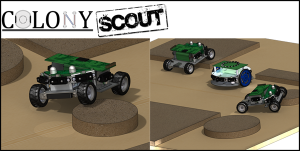
Extending the Scout robot platform

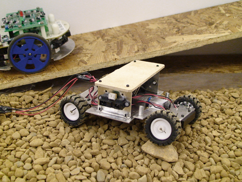
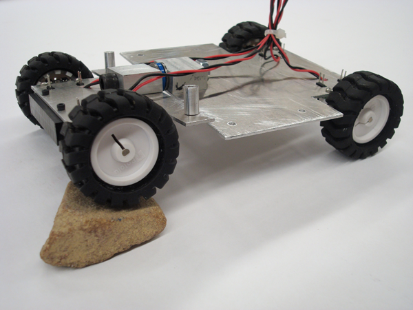
The Scout is a capable platform on its own, able to traverse rough terrain and avoid obstacles at high speeds. Even so, one of the main strengths of the Scout is its (rear) accessory interface.


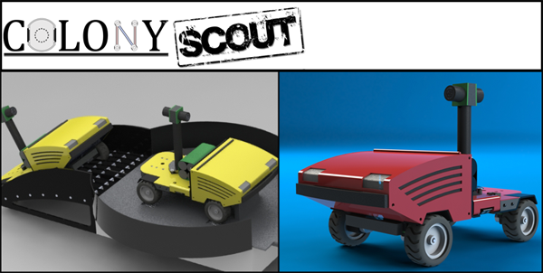
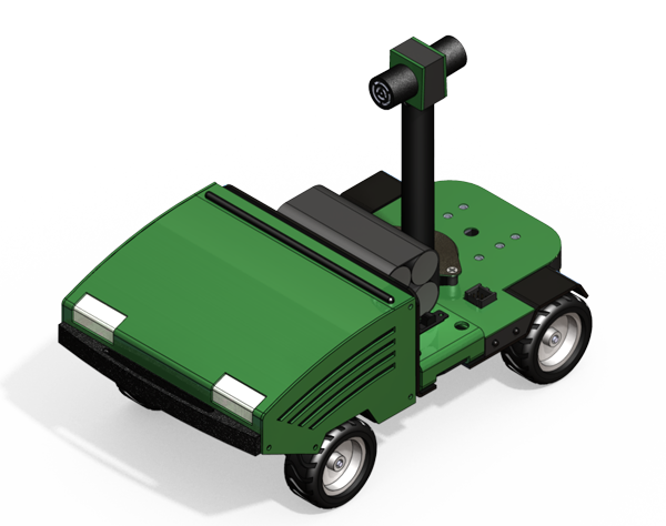
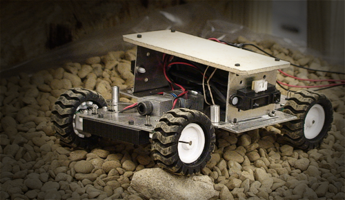
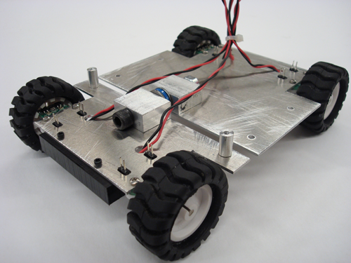
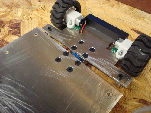
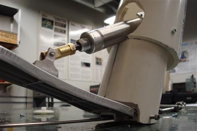
Many research platforms were designed around a single purpose or only provide the ability for "expansion" cards in the form of networked printed circuit boards. Researchers working on the Scout platform won't be restricted to the current sensor/manipulation package, nor will they be constrained to fixed size add-on modules. The Scout provides power, data, and hardware attachment points to allow a variety of mechanical or sensor add ons. You can see the six threaded hard points in the rear of the vehicle, as well as a thrust bearing for pivoting accessories.

Dumb vs. Smart
The accessory interface attempts to be as non-restrictive as possible while providing both basic and advanced functionality to the designer. To that end we've denoted two classes of accessories, those with "smarts" (onboard processor) and those without. Both classes of accessories must identify their type/function as matched against an accessory database stored on each robot. This allows the OS to configure communications between the ARM and AVR at the bandwidth necessary for desirable performance.

"Dumb" Add-Ons
Dumb accessories are simple devices that only require power and access to an analog (input) or (2) digital I/O. This might be as simple as a wagon with a potentiometer for tracking position and a switch to indicate whether a load is present. Basic I/O pins are provided by the AVR.

"Smart" Add-Ons
A smart accessory has its own on-board microcontroller that handles all the low-level control. An I2C connection straight to the ARM9 processor is provided. Smart accessories can still access the AVR pins, although it should rarely be necessary. The forklift shown below is a "smart accessory" since it requires active control of the lift position and active monitoring of the RFID reader and loading.


Forklift/ Autonomous Distribution Warehouse
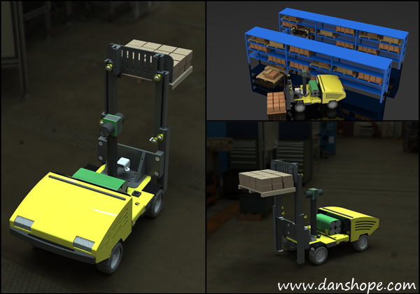
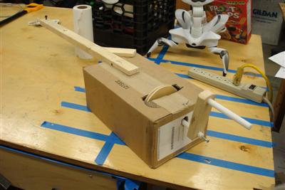
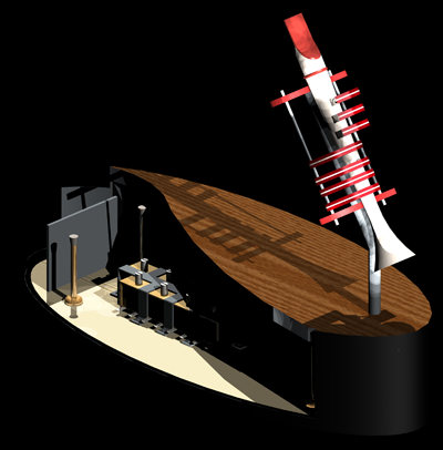
My favorite accessory to date, the forklift gives the Scout 0" to 6"+ lift capacity. Pulling tasks off the server, robots will autonomously move packages around, pausing to recharge when necessary. Mobile robots are already in use in semi-automated distribution centers, such as Staples.

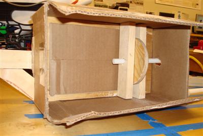
The mechanism uses a three stage lift actuated by a cable pulley system. The RFID reader sits behind the carriage. When closed, the forklift does not extend into the sonar's sensing cone, enabling use of rear ranging data. The charging contacts also had to remain exposed so the robots can dock for battery refueling.


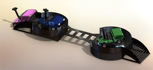
Dig & Haul/ Autonomous Excavation

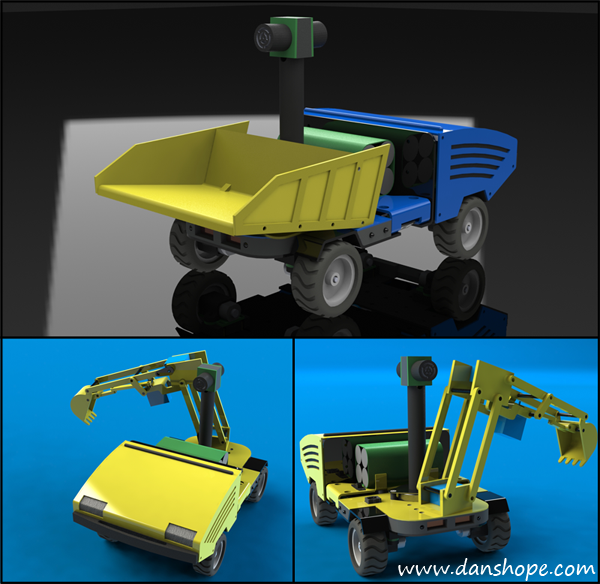
Design to test cooperation between two or more robots, the dig and haul attachments provide an entertaining and challenging application of swarm robotics.

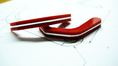
The designs both employ micro servos for actuation. Hauler also uses a load cell (force sensing resistor) to determine when the bucket is full and instruct the digger to halt loading.

Hauler could easily be implemented as a "dumb" accessory, but Digger requires it's own micro due the increased complexity of the control and positioning system.

What next?
Plans are in place to design a simple webcam interface, surveillance package, and a pan/tilt semi-automatic cannon. Have an idea of a sweet accessory? Add your concept to the comments below! I love hearing new ideas, no matter how radical.

Labels: , , , , , , , , , , , , ,


Thursday, November 5, 2009

Designing & Testing Robots: Colony Scout

Colony Scout Updated Design
Between classes, eating, and sometimes sleeping I've been hard at work refining the Colony Scout robot. The core feature set has remained the same -- four wheel drive, rocker pivot platform powered by a lithium ion pack. The sensor package includes a front bumper, dual sonar rangefinders, battery level monitoring, localization beacons, xbee communications, wheel encoders, yaw gyroscope, and three axis accelerometer.

Shown here in green (one of many colors), the Scout now sports a vented enclosure for the electronics. RGB (multicolor) LED "headlights" shine out the front hood, which is magnetically clasped for easy access to the processing board.


The team has been hard at work designing the Scout board, which runs an ARM9 core mated to an ATmega 128A as a coprocessor. The ARM9 does the heavy lifting but leaves the very important role of gathering sensor data and driving the motors to the lower powered AVR chip.

Board design is custom and includes components specific to the platform. We are looking into POE (power over ethernet), USB, and external charging to power the system.

Scout will run a Linux RTOS -- as yet to be decided. Linux brings a lot of functionality to the table but also has its own quirks that will be interesting during development and testing. We hope to have a first run dev board in testing by December.


Diagnostic Station
Testing and validating the robot design only goes as far as production. The diagnostic station aids the maintenance process over the lifetime of the robot(s).

I went for a pipelined design whereby tests are separated spatially to allow faster throughput with multiple robots. This results in an elongated testing platform, but it still measures in under a yard...so far :-)

Assuming the robot can navigate to the station, it will ascend the ramp and proceed through the three stages. All tests and robot maneuvers are controlled by the Colony server, which handles scheduling and task assignments for all the robots.


Stage 1: Chassis Dyno & rBOM Tester
The motors and encoders are tested across the speed range of the robot. A sequence of tests is also performed with loading on the dyno rollers. This simulates the robot driving across different terrains.

Stage 2: Cliff Bridge
Between the two larger stations, the bridge tests the three cliff sensors through several cycles (see ladder-like design). This comes after the encoders/motors are calibrated for straight line driving. We don't want robots to go splat during a maintenance run!

Stage 3: Gyro & Accelerometer Station
The final and most complex station latches onto the robot and spins it for gyro testing. Accelerometer tests are also performed by spinning and tilting the robot. I'm still designing the internal mechanisms -- should be interesting.

Dyno Station Mock up (who doesn't love Legos(R)?)

Other News
I've also been working on the design and function of the charging station. So far it's pretty sweet with a low profile, modular design. I'll try to post some renders and details up soon!


Labels: , , , , , , , ,


Wednesday, June 24, 2009

Sharp IR Rangefinders and Arduino: Make your Robot Smarter

Adding distance or proximity sensors to your robot is a great way to start exploring your environment intelligently. Rangefinders allow a non-contact method of “seeing” obstacles and can be employed in mapping and maze solving as well.

The Sharp family of infrared (IR) rangefinders is very popular amongst hobby roboticists because they are low-cost and easy to interface with (Voltage, Ground, and Signal). These hook up to a single analog input pin on the Arduino or similar microcontroller systems. There are a few caveats to watch out for though.

If your application is very time sensitive and needs tightly controlled, you’ll want to find out how long polling your sensor(s) takes. The Sharp sensors output an analog value (as a voltage), but microcontrollers only understand digital values (1 or 0), so that analog value has to be converted. Analog to digital conversion is pretty fast, but it can introduce some delays.

The sensors are also very noisy, meaning the analog output signal has a lot of "jitter" -- 20cm does not always equal 280, etc. Your code will have to account for this jitter, so you'll need to collect some real-world values to build your sensor model. This problem is exacerbated by the next issue, but can be overcome with a little bit of thought and time. I don't provide you the solution here because it's really dependent on your application. There is, however, a tool to help you evaluate your sensors (see below).

Moving on, take a look at this graph:

You’ll notice something interesting here – the graph has a weird curve and isn’t linear at all. This becomes tricky when trying to teach the robot to understand distance from the analog output of the sensor.

There are a few ways to get around this. If all you want is a simple threshold say “nothing closer than 20cm” then you can simply run a few tests with an object placed 20cm away from the sensor, and then hardcode that value into your program. Generally it’s a bit more complicated, if you want the program to understand varying distance.

Method 1:
Approach: Find a best-fit curve (generally exponential or polynomial) using a statistics package (Excel, R, Minitab)
Pros: Easy to implement, gets you started fast.
Cons: Requires floating point math, which isn’t natively supported by most microcontrollers. You can still use floating point, but it’s slow and inefficient in most cases.

Method 2:
Approach: Gather some data points and create a look up table of values. Your code will linearly interpolate values between each data point (ie, 5cm=600, 10cm=300, etc).
Pros: Uses integer math which is fast and efficient
Cons: Takes up more memory and doesn’t give exact values

Method 2 is the preferred approach as most embedded system developers take great pains to avoid floating point math. You can have some floating point math on the Arduino and be alright. I have a large (6KB) program right now that has floating point littered all over the place (it’s necessary for this code) and execution time runs just fine.

To help with gathering your data for both method 2 and simple thresholding I wrote a quick little application that interfaces with the Arduino’s serial connection. This app will pull your data in and calculate some basic statistics such as standard deviation, mean average, and range of values. You can store the data for future computation and reference.

Download the IRanalzyer at http://www.danshope.com/calton/ir.html

To use the IRanalyzer you need to send values from the Arduino. Here’s a sample sketch to get you started:


#define SerialSpeed 115200 //typical values are 9600 or 115200
#define SampFrequency 10 //sampling frequency in Hz (cycles per second)
#define AnalogPIN 0 //define your pin here

int mDelay;

void setup()
{
Serial.begin(SerialSpeed);
mDelay = 1000/SampFrequency; //calculate delay for proper sampling rate
}

void loop()
{
delay(mDelay); //delay in milliseconds
Serial.println( analogRead(AnalogPIN) ); //reads the analog port and prints value over serial
}

Labels: , , , , , , , , , , , ,


Wednesday, June 3, 2009

Inside the $400 Colony Scout: Robot on a Budget

Now that I posted some videos of the Colony Scout in action, I’ll discuss the platform in a little more detail.

The basics: It’s a compact (4.75”x6”), four wheel-drive robot equipped with an array of IR distance sensors, automatic recharging capability, and other features yet to come. The current talk is to use an ARM7 based board running at 40MHz, paired with an unspecified ATMega for additional I/O.

Some background: The goal of the Colony project at the CMU Robotics Club is to develop a low cost swarm robotics platform capable of structured coordination to carry out tasks too difficult for a single machine.

Colony has been around for several years and has made great strides with a few robot upgrades along the way. The team is prepping the Scout as a potential replacement for the current ATMega 128L based robots.

The goal: The Scout is a deviation from the 2-wheel differential drive robots used in the past. While a common and versatile form factor, the two wheeled platform balked at any non-level terrain. Even driving up ramps or over wires can become an issue. Scout is designed to expand the exploration options beyond level and rectangular environments.

What’s new? Faster processors and an efficient code base will permit the Scout to actively respond to a complex environment. The new sensor array extends the current 5 IR sensors to 7 for additional range and cliff detection. A bump switch returns for the front bumper to detect obstacle collision (useful when purposely pushing objects).

Each of the Pololu wheels comes equipped with a quadrature encoder that gives ~3mm linear accuracy. The 10x12mm micro metal gearmotors are lighter, faster, and stronger than the Solarbotics GM8s on the current robots. Using four motors does draw more current, so the battery is upped from a 6V 2200mAh NiMH pack to a beefy 7.2V 4000mAh Li-Ion pack.

Conclusion: The Colony Scout is a tough little machine that can cross rough terrain while employing a multitude of sensors, all for a sub-$400 cost per robot. Plans are in place to make the robots “smarter” than ever before, and able to respond to the environment faster and in a more coordinated manner.

Summer 2009 is all about prototype testing – learning about the platform and its capabilities and limitations, so stay tuned – More videos and posts will be coming your way!

What do you think? What types of functionality, from line sensing to 3D mapping, do you think a cheap robot should have?

See http://www.danshope.com/blog/2009/05/putting-colony-scout-robot-through-its.html for more pics and vids on the Colony Scout.

Labels: , , , , , , ,


Sunday, May 31, 2009

Putting the Colony Scout robot through its paces

The new Colony Scout platform was up and running for a few hours today as I continued testing the AWD system. Scout is a prototype platform for swarm robotics at the Carnegie Mellon Robotics Club.


We remade the baseplate out of 6061 aluminum on the CNC mill as the previous handcut plate was too soft and imprecise. I wanted the alignment of all the motors/wheels to be as consistent as possible for straight tracking with minimal correction from software.

The headers you see sticking up beside each wheel are for quadrature encoders - the encoders give the robot about 3mm linear resolution, which is decent for a vehicle of this size.


Another exciting component added today was the rocker, which allows the front and rear axles to swivel (vertically). This allows all four wheels to contact the ground during most terrain crossing, improving traction. The updated platform outperforms the Scout of two days ago, which featured a rigid baseplate.


The new components have a high degree of polish accomplished by good design and machining practices. Our club machine shop allows us to turn out quality parts and have a fast turn around time from concept to prototype.


Click through to http://www.youtube.com/watch?v=ePaPGyjW2uk to watch the video in HD.

There's also some great tests on http://www.youtube.com/watch?v=fyRmg570KJw from a few days ago.

Keep tuned for more updates this week!

Labels: , , , , , , , , ,


Monday, April 6, 2009

That's Just Boulderdash!

The Carnegie Mellon team participated at the 2009 ASME Mars Rocks competition in Dayton, OH a few weekends ago. You can watch our robot, Boulderdash here http://www.youtube.com/watch?v=oY4gXETGdrw or see a competition recap at http://www.youtube.com/watch?v=nQIlcrWNil0.

I'll be posting more about the design of our rock sweeper soon! Until then enjoy the videos. Thanks to Jimmy Bourne for the media editing.

Labels: , , , ,


Thursday, March 12, 2009

Do You Know How to Arduino?

I had a great day prototyping with new Arduino Duemilanove. Other than the frustaingly long name we got along pretty well!

The board came from SparkFun along with a protoboard -- I didn't get the protoshield yet, but it's only another $16 so it might be a future purchase. Also arriving today was the compact accelerometer breakout board from RobotShop. One box came by snail mail, the other by UPS, so it was quite exciting when they arrived literally within minutes of each other.

The Duemilanove is a great board -- solid components, automatic power switching, plenty of IO, and an upgraded ATmega chip. I'm definitely going to like having the extra storage on board for my new project.

I had to do a lot of fiddling to get the accelerometer to work well, but most of this was software tweaking. The actual circuitry took all of fifteen minutes and the arudino sketch was really fast.

#include

void setup()
{
  Serial.begin(115200);
}

void loop()
{
  Serial.print("X");
  Serial.print(analogRead(2));
  Serial.print(",Y");
  Serial.print(analogRead(1));
  Serial.print(",Z");
  Serial.print(analogRead(0));
  Serial.print("|");  
  delay(250); 
}
There's the arduino code to read three analog values from the accelerometer -- I've pushed them into a format that looks like 'X000,Y000,Z000|' for ease of parsing. The code sets up the serial communications at 115200, a common speed for PC work.

If you're hooking your board up to say a BASIC stamp or other board, the speed will typically be 9600baud. This is simple - just change the setup code to say Serial.begin(9600);.

So, back to the filtering issues -- the Arduino board runs at 5V, so it expects an analog pin to input between 0 to 5V. The accelerometer outputs from 0 to 3.3V, so it effectively loses 33% of the full range of the arduino pin.

Arduino outputs a signal (when it reads the pin) between 0 and 1024. For an accelerometer, 0 means full negative acceleration, while 1024 means full positive accleration. What "Full" means varies on your accelerometer sensitivity range. Mine is adjustable from +/-1.5g to +/-6g (g==multiples of gravity, i.e. 9.81m/s^2).

To graph the data I needed to scale my output == instead of 1024 being max, 675 was the new maximum; 0 stayed the same. There was also a dropout issue where the signal would drop to full negative (0V, 0 output) every few seconds. This was determined to be a software issue, so I simply discarded any input that matched this characteristic.

It's pretty trivial in most langauges to set up a serial port monitor -- you can also simply use the serial port monitor right in the Arduino IDE, but you can't do anything except watch the raw data scan by....pretty useless for actual work, but great for debugging.


I consider myself a visual learner, and assuming you're the same -- here's the final accelerometer data. The green is the Z axis, red == X axis, and blue == Y axis. The X and Y axis average to around zero, which is good == the board was level and stationary. The green axis is hovering below the rest...do you know why?

Yep, we still haven't figured out how to turn gravity off. I think that's a good thing! If we're properly calibrated, the Z axis will be registering an average of 1g when standing still.

Well, I'm off to prototype more stuff! Now to try a Sharp IR rangefinder and some more serial data transfer using the digitial pins (0 & 1).

Labels: , , ,


Monday, February 16, 2009

RobOrchestra Update: Bass Drummin' Bot

This past Friday was quite productive for the RobOrchestra team as two instruments were constructed -- the first two for this year.


A few of the guys got together Friday afternoon and built a hurdy-gurdy prototype. The stringed instrument is constructed from a cardboard box and plywood frame. So far the instrument sounds decent when turned, but needs some work on amplification. Using material other than cardboard should definitely help the acoustics...


Fellow RobOrchestra member Andrew Burks and I spent the better part of Friday night (yay social life) working in the shop on the bass drumming robot (as yet unnamed). Andrew made an awesome SolidWorks model which we used as a reference for the parts.

The basic design uses a Bimba air cylinder limited to ~0.5" stroke under 30psi. The cylinder has pivot points at both ends. The pivot points took a lot of machining as we had some pre-existing components that needed to be modified to allow attachment points. One screw up and we were out those parts and had no spares. Fortunately, everything went off without a hitch.

Once the cylinder has pivots at both ends, one end gets attached to the "shoe" of the pedal, the other end inside our robo-leg. We have some sweet plans for decorating said leg -- but until then...


here's a truly amazing picture of yours truly, oh how flattering :-)

Labels: , , , , ,


Tuesday, November 25, 2008

Flutophone 2008: Incremental Update

The flutophone project has been around since the beginning of RobOrchestra, though not in its current form or even with its current name. Started as the "penny-whistle", the project was cobbled together with an old tin whistle, a few solenoids, some plastic fingers, and a little bit of engineering. Penny whistles are basically a long metal tube with holes along the length. Once the instrument was mounted on a base, plastic fingers were built around it that used the "on" or activated setting of the servo to close off an individual hole with a foam ear plug. There were 7 solenoid/arm pairs, one for each hole.

In 2006, a fresh team of undergraduates joined the team, ready to begin and tackle any challege. There were a few problems with this design that the team set out to fix. First, the holes weren't being sealed adequately by the ear plug design. There was some confusion as to whether the soldenoid driven arm didn't have enough force, or if the foam was simply too stiff to conform to the hole and create a good seal. We decided to address both concerns. In order to create a better seal we decided to use some light rubber discs, the kind that you buy to place under objects to prevent a surface from marring. The other aspect of the better seal was switching to a more geometrically desireable instrument, the flutophone. Flutophones have flat surfaces above each hole versus the highly curved surface the penny whistle provided. These changes helped alleviate the biggest challenge - making sure we could produce sound.

The second issue is that the solenoids clacked so loudly, even if the penny whistle/flutophone could get a few notes coaxed out, they would be drowned by metal clanging. We decided to build an enclosure around the solenoids and allow the acutators to pass through a "lid" to the fingers.


The "suspension bridge" design (cutaway view) modeled in SolidWorks

This is the design that we arrived at. We called it the "suspension bridge" approach since we had lots of cables running down sort of like a bridge. This design utilized a main "vertical" shaft that supported the flutophone, finger assembly, and the air tubing. The fingers were mounted to the shaft on dual axles that incorporated spring returns for hole closure. Cables attached to the fingers ran across a pivot point and down into the enclosure such that activating a solenoid would lift the corresponding finger, breaking the seal.

We designed the angles of the instrument such that the cables ran orthogonal (90deg) from the shaft, thus directing all of our force from each solenoid along the action of the finger. This stretched the base to around 18". I made the base out of fiberglass and fiberboard for the strength and light weight characteristics. We determined that the height of the enclosure should be ~3inches to allow clearance for the solenoid plungers. 

Much to our delight, door stops are exactly 3inches long, which provided both the clearance we wanted and had a nice side effect. Since the end of the doorstop is rubber, it provided some shock absorber or damping charactersitics between the "lid" and the enclosure. We also placed felt discs underneath the base to damp the vibrations between the enclosure and the surface it was sitting on. Most of these changes were made to reduce the obnoxious noise the solenoids made.


Plastic composite fingers were strong and stylish

The fingers were a lot of fun to design and construct. I used SolidWorks to model the entire assembly, and created the fingers in this context. I tried to mimic a humanoid shape so that they looked appealing (staying away from the uncanny valley though) and natural. The pivot point of the fingers was designed so that rotating it from its resting position would result in "perfectly" vertical motion (at the first instant). Due to the sine effect there would be little translation of the fingertip side to side, thus most of the displacement would be above the hole surface. If it had been designed differntly, the finger pad would need to rotate across the surface of the flutophone hole, shearing the pad and possibly breaking it off the fingertip.

The fingers were constructed by a three layer laminate. I used some 1/8" red plastic and some thinner white plastic, gluing them together and letting them dry overnight. Then I printed out my design from SolidWorks onto Avery address labels (full adhesive) so that I could simply trace my design while I was cutting each piece out. This was quite the tedious process since each finger was less than 3" long.

2006's design was "pretty" but not functional. We had designed with the best intentions but forgot that oh so helpful acroynm, KISS (Keep It Simple Stupid). You'll probably see me refer to that a lot because so often, the simplest and most elegant solution is the best in terms of cost, manpower, and resources. Plus, a simple solution is easier to change later down the road (in general).


The final design (prototyping material)

Thus, in 2007 I came back with new fervor. I was the last of the original flutophone design group (other members of RobOrchestra were still around), so it became my "pet" project. The design I came up with above is very compact and uses servos for acutation in both directions (open and closed). This was very important since we had tried both actuation==open and acutation==closed with marginal success. The main body bracket that housed the servos contained the entire structure of the new 'bot. We used HS-422 servos (72oz-in torque) which were more than we needed, but I got a good deal on them and we can always reuse them in the future.

The design uses 7 servos, one for each hole. The finger design is similar to that used in the past, just updated for the geometry of the new design. Each servo is connected a finger by a chain and sprocket (1:1) mechanism. For the most part this functions very well, but I had a few issues with keeping tension on the fingers. It was difficult to maintain a calibration on the position relative to the flutophone since there was so much backlash in the system. That part of the design is being updated to fix the backlash issues.

You can see a video demonstration of flutophone on Youtube. In the video, I walk you through the features of the robot and how everything is intended to work. On another video I may upload later, it is actually playing Mary Had a Little Lamb. The great thing about that video is that I was simultaneously the provider of air, program controller, and photographer. Yikes!

The current design is being finalized this year-the main thing that it needed was a few idler pulleys to maintain tension on the chains. Once that is complete she'll be as good as new and ready to play. I'm hoping that we can get the whole thing machined out of plastic so that it is more durable and more precise. We are also working on loading servo controller code onto the RobOrchestra boards, so it can play with the rest of the group. If you want to see more about flutophone, just leave a note in the comments!

Labels: , , , ,


Monday, November 24, 2008

Snarebot 2008: The Little Drummer "Boy"

The RobOrchestra Snarebot is finding its legs..err arms this year. The project is a few years old and has experienced incremental improvements over its lifetime. This time around we are looking to make a dramatic improvement based on the existing design and input from drumming consultants. We want to make it as realistic at drumming as possible with good dynamics and a pleasing sound.


The old design used two large solenoids pulling on cables to actuate the drum sticks. The wires were connected to specialized rubber holders that had built in compliance to allow the sticks to rebound quickly off the drum surface. These work really well and were one of the biggest components in the success of snarebot 1. What the 'bot lacked was good control over speed and dynamics - since solenoids are either "on" or "off", that's all you could coax out of it. Since there was a single pivot point, it was also impossible to induce different velocities out of the drum strike.


This is the design I envisioned last year - a small, portable device that could fit on any standard size drum. It was actually really neat, and I built a small prototype for the shell and legs. When you rotated the center handle the legs would extend or contract depending on the direction you turned. Since there wouldn't be much force opposing the legs (all downward) they would remain extended and the 'bot would perch happily on the edge of the drum.

This worked pretty well, but only left about an 8 diameter area in which to fit the drum stick mechanism. We found out that short sticks sound really flat since you couldn't get the pleasing resonance you normally hear from a snare drum. The device made had about 4" arm and could hit every 25ms, so speed wasn't an issue.


My sketch for this years' redesign is above. Its larger offset design allows for greater movement and the use of standard drum sticks, so we avoid the resonance issues of the past design. It will incorporate cable drives, solenoids, and servo motors to provide a wide range of speed and dynamics control lacking in Snarebot 1. The drawing isn't exactly to scale as the drum sticks actually stretch across the diameter of the drum, but after taking some measurements I verified the design is doable. Now it's just a matter of finding time to sit down and CAD model it in SolidWorks.

Some people have expressed concerns about latching onto the tuning bolts, but others say we should be fine. I've designed the 'bot this way so that we can eliminate the large clunky stand. It worked out pretty well for Snarebot 1, since you could easily reposition it, but we have something up our sleeves for this design that can accomplish the same thing.

You can't see it from this drawing, but the base will incorporate motorized translation and rotation so the snarebot can target different areas of the drum. Now, we're starting to talk about a lot of motors here, but each RobOrchestra controller board has ~16 outputs, so we should be fine. Hmmm....how about some neon underlighting?

Labels: , , , , , , , ,


Subscribe to RSS Feed
Subscribe to DanShope.com
Who writes This Stuff?
Daniel Shope is the site owner and moderator of DanShope.com, a portal dedicated to robotics and engineering. Dan is currently a student at Carnegie Mellon University and is pursuing dual degrees in Mechanical and Biomedical engineering.

View Daniel Shope's profile on LinkedIn
Advertisements