<body bgcolor=#000033"><script type="text/javascript"> function setAttributeOnload(object, attribute, val) { if(window.addEventListener) { window.addEventListener("load", function(){ object[attribute] = val; }, false); } else { window.attachEvent('onload', function(){ object[attribute] = val; }); } } </script> <iframe src="http://www.blogger.com/navbar.g?targetBlogID=4830160160028833890&amp;blogName=DanShope.com&amp;publishMode=PUBLISH_MODE_FTP&amp;navbarType=BLUE&amp;layoutType=CLASSIC&amp;searchRoot=http%3A%2F%2Fblogsearch.google.com%2F&amp;blogLocale=en_US&amp;homepageUrl=http%3A%2F%2Fwww.danshope.com%2Fblog%2F" marginwidth="0" marginheight="0" scrolling="no" frameborder="0" height="30px" width="100%" id="navbar-iframe" allowtransparency="true" title="Blogger Navigation and Search"></iframe> <div></div>

Friday, November 6, 2009

Extending the Scout robot platform

The Scout is a capable platform on its own, able to traverse rough terrain and avoid obstacles at high speeds. Even so, one of the main strengths of the Scout is its (rear) accessory interface.
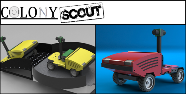

Many research platforms were designed around a single purpose or only provide the ability for "expansion" cards in the form of networked printed circuit boards. Researchers working on the Scout platform won't be restricted to the current sensor/manipulation package, nor will they be constrained to fixed size add-on modules. The Scout provides power, data, and hardware attachment points to allow a variety of mechanical or sensor add ons. You can see the six threaded hard points in the rear of the vehicle, as well as a thrust bearing for pivoting accessories.

Dumb vs. Smart
The accessory interface attempts to be as non-restrictive as possible while providing both basic and advanced functionality to the designer. To that end we've denoted two classes of accessories, those with "smarts" (onboard processor) and those without. Both classes of accessories must identify their type/function as matched against an accessory database stored on each robot. This allows the OS to configure communications between the ARM and AVR at the bandwidth necessary for desirable performance.

"Dumb" Add-Ons
Dumb accessories are simple devices that only require power and access to an analog (input) or (2) digital I/O. This might be as simple as a wagon with a potentiometer for tracking position and a switch to indicate whether a load is present. Basic I/O pins are provided by the AVR.

"Smart" Add-Ons
A smart accessory has its own on-board microcontroller that handles all the low-level control. An I2C connection straight to the ARM9 processor is provided. Smart accessories can still access the AVR pins, although it should rarely be necessary. The forklift shown below is a "smart accessory" since it requires active control of the lift position and active monitoring of the RFID reader and loading.


Forklift/ Autonomous Distribution Warehouse
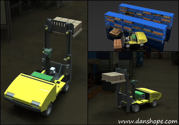
My favorite accessory to date, the forklift gives the Scout 0" to 6"+ lift capacity. Pulling tasks off the server, robots will autonomously move packages around, pausing to recharge when necessary. Mobile robots are already in use in semi-automated distribution centers, such as Staples.

The mechanism uses a three stage lift actuated by a cable pulley system. The RFID reader sits behind the carriage. When closed, the forklift does not extend into the sonar's sensing cone, enabling use of rear ranging data. The charging contacts also had to remain exposed so the robots can dock for battery refueling.


Dig & Haul/ Autonomous Excavation
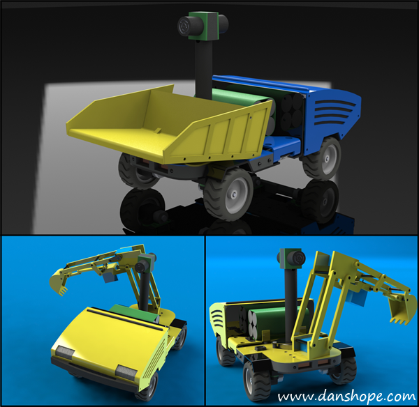
Design to test cooperation between two or more robots, the dig and haul attachments provide an entertaining and challenging application of swarm robotics.

The designs both employ micro servos for actuation. Hauler also uses a load cell (force sensing resistor) to determine when the bucket is full and instruct the digger to halt loading.

Hauler could easily be implemented as a "dumb" accessory, but Digger requires it's own micro due the increased complexity of the control and positioning system.

What next?
Plans are in place to design a simple webcam interface, surveillance package, and a pan/tilt semi-automatic cannon. Have an idea of a sweet accessory? Add your concept to the comments below! I love hearing new ideas, no matter how radical.

Labels: , , , , , , , , , , , , ,


Monday, November 24, 2008

Snarebot 2008: The Little Drummer "Boy"

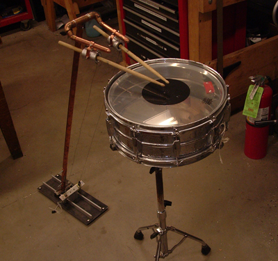
The RobOrchestra Snarebot is finding its legs..err arms this year. The project is a few years old and has experienced incremental improvements over its lifetime. This time around we are looking to make a dramatic improvement based on the existing design and input from drumming consultants. We want to make it as realistic at drumming as possible with good dynamics and a pleasing sound.


The old design used two large solenoids pulling on cables to actuate the drum sticks. The wires were connected to specialized rubber holders that had built in compliance to allow the sticks to rebound quickly off the drum surface. These work really well and were one of the biggest components in the success of snarebot 1. What the 'bot lacked was good control over speed and dynamics - since solenoids are either "on" or "off", that's all you could coax out of it. Since there was a single pivot point, it was also impossible to induce different velocities out of the drum strike.


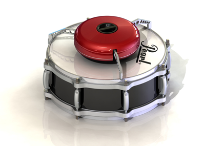
This is the design I envisioned last year - a small, portable device that could fit on any standard size drum. It was actually really neat, and I built a small prototype for the shell and legs. When you rotated the center handle the legs would extend or contract depending on the direction you turned. Since there wouldn't be much force opposing the legs (all downward) they would remain extended and the 'bot would perch happily on the edge of the drum.

This worked pretty well, but only left about an 8 diameter area in which to fit the drum stick mechanism. We found out that short sticks sound really flat since you couldn't get the pleasing resonance you normally hear from a snare drum. The device made had about 4" arm and could hit every 25ms, so speed wasn't an issue.


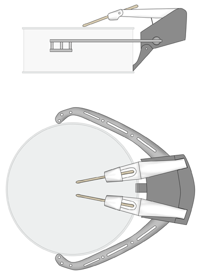
My sketch for this years' redesign is above. Its larger offset design allows for greater movement and the use of standard drum sticks, so we avoid the resonance issues of the past design. It will incorporate cable drives, solenoids, and servo motors to provide a wide range of speed and dynamics control lacking in Snarebot 1. The drawing isn't exactly to scale as the drum sticks actually stretch across the diameter of the drum, but after taking some measurements I verified the design is doable. Now it's just a matter of finding time to sit down and CAD model it in SolidWorks.

Some people have expressed concerns about latching onto the tuning bolts, but others say we should be fine. I've designed the 'bot this way so that we can eliminate the large clunky stand. It worked out pretty well for Snarebot 1, since you could easily reposition it, but we have something up our sleeves for this design that can accomplish the same thing.

You can't see it from this drawing, but the base will incorporate motorized translation and rotation so the snarebot can target different areas of the drum. Now, we're starting to talk about a lot of motors here, but each RobOrchestra controller board has ~16 outputs, so we should be fine. Hmmm....how about some neon underlighting?

Labels: , , , , , , , ,


Sunday, November 23, 2008

Creation of a robotic arm


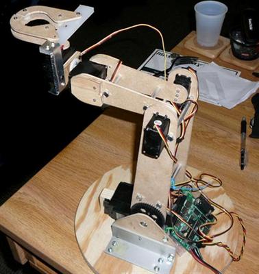
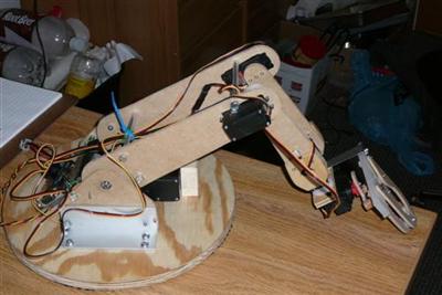
This is the robotic arm I built to demonstrate at the Cub Scout meeting a few days ago. It's main construction material is hardboard -- sort of like clipboard material but a little bit more flexible. Ideally it would be built out of aluminum, but hardboard is very fast to shape and drill through, so in the interest of time it was chosen. The total project time was under 48 hours from start to finish, which also included sleeping, eating, and classes in the middle.


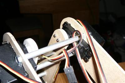
The main shoulder joint is driven by a Hitec HS-805BB servo, a real monster. I like this servo a lot because it can pretty much give whatever you ask from it. Stall torque is rated at 343oz-in and I also had a gear reduction on the shoulder joint that increased the torque by about 1.75x.


The elbow joint was a lot of fun because I chose to use two HS-311 servos in conjunction. This configuration provides stability for both sides of the joint and bumps up the maximum torque. Since I still had a lot of mass to control outset from the elbow the extra capacity was necessary. These servos produce around 42oz-in of stall torque, which was sufficient for this design. In the actual controller code the servos rotate in opposite directions, so I had to be concious of them trying to fight each other. Overall this joint performed the best and was super fast!


Here's a side view of the whole 'bot. The gripper mechanism is pretty neat but not functional. You can sort of deduce this from the one piece of aluminum sheet metal holding it on. I ran out of time to make it work well, but decided to attach it for asthetic purposes. The basic mechanism has a rotating cam that spreads the two fingers. The grip is supplied by spring returns on each finger. It also features a passive locking system on the cam when the fingers are completely closed.

The large gear on the shoulder joint gave me a lot of problems since it wasn't a very high quality part. The interface between the HS-805BB servo and the shoulder gear was difficult to maintain and the joint frequently slipped when it was moved too fast. In an attempt to maintain that joint better I added the large aluminum brackets you see here. They did help a lot, but still couldn't maintain the level of consistency I wanted from the arm. I plan on re-machining everything from aluminum when I build the snare-bot arm (similar design) for strength and precision.


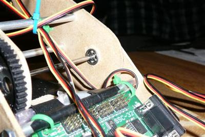
You can see the press-fit bearings used at the shoulder joint. It was pretty epic putting precision bearings into fibrous hardboard material. They fit quite snug, looked pretty, but were totally over-engineered for this choice of construction material. You can also see the controller board here -- a Lynxmotion SSC32. This board is my favorite serial servo controller I've used so far with 32 outputs, daisy chaining capabilities, a wide range of baud rates, and a relatively compact footprint.

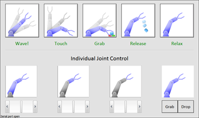
The controller board was connected by serial cable to a laptop running Windows and a serial servo controller program I wrote. This is the "kid" version of the software which has pre-scripted macros for cool demonstrations. I typically use a stripped down version of this program to run all of my 'bots that use the SSC-32. If you are interested in the board go to Lynxmotion and check it out. If you get or have the board and want the basic software (8 channel control and terminal window) send me an email!


Labels: , , ,


Subscribe to RSS Feed
Subscribe to DanShope.com
Who writes This Stuff?
Daniel Shope is the site owner and moderator of DanShope.com, a portal dedicated to robotics and engineering. Dan is currently a student at Carnegie Mellon University and is pursuing dual degrees in Mechanical and Biomedical engineering.

View Daniel Shope's profile on LinkedIn
Advertisements